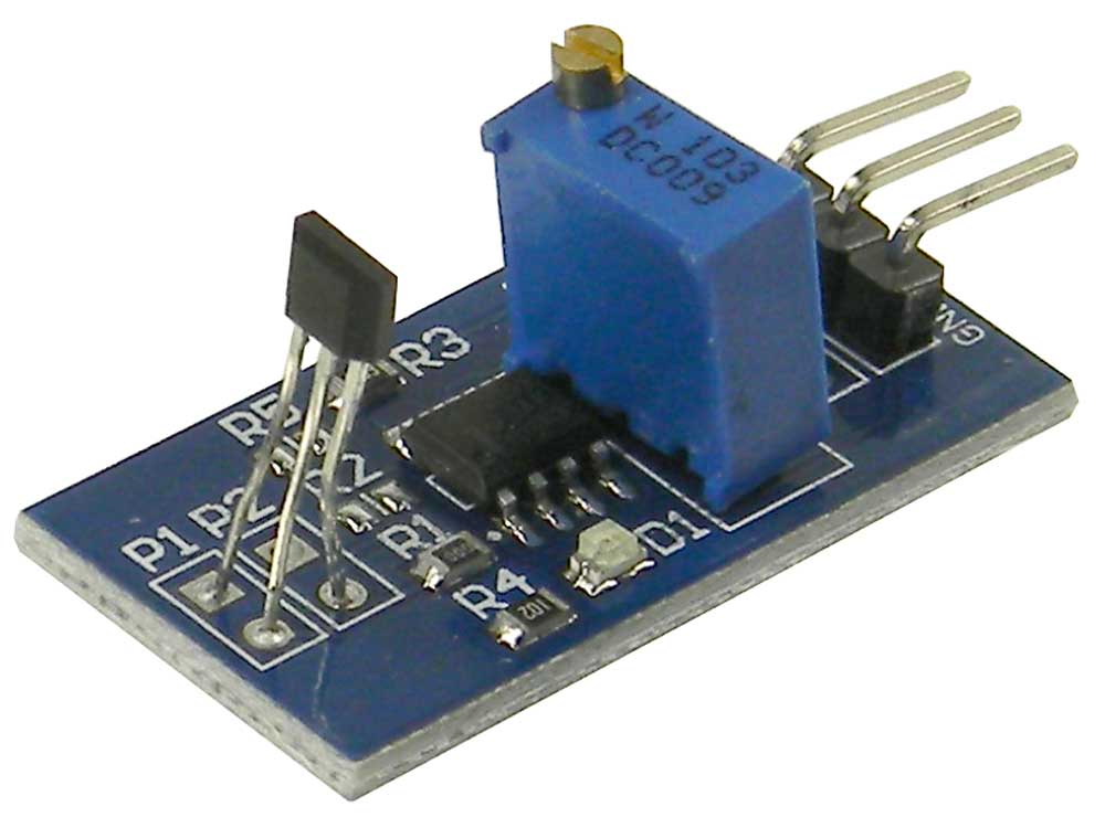
Wiring a Hall Effect Speed Sensor Simplified Guide Circuit Diagram I'm using an ominpolar hall effect sensor from Allegro I think, I've used these in the past for another project and it seems to be working fine. It's reading the magnet, and I've done the basic sketch to illuminate the on board LED of the UNO. The screen is a basic 128 x 32 OLED thing, and again it's functioning well.

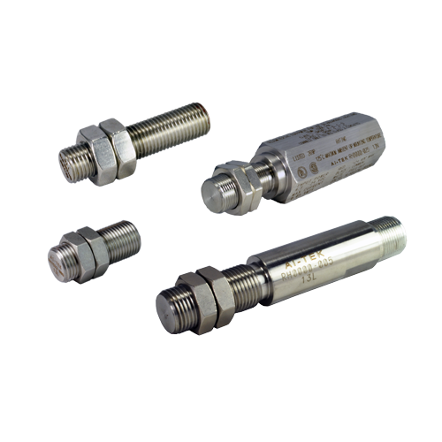
A Hall-effect sensor varies its output voltage in response to a magnetic field. Hall-effect devices are used as proximity sensors and for positioning, speed, and current detection. They are widely used in motor control systems. A Hall-effect sensor is a long-lasting solution because there are no mechanical parts to wear down over time.
How to Use a Hall Effect Sensor With Arduino Circuit Diagram
Control a Relay with Arduino and Hall Effect Sensor. The circuit diagram for controlling a 5V Relay Module with Hall Effect Sensor and Arduino is shown below. Code. Working. The working of this circuit is very simple. Whenever the Hall Effect Sensor is subjected to a magnetic field, it toggles the Relay (as per the code). Applications of Hall
Hello, I am trying to measure the speed of a bicycle wheel using a hall effect sensor. I am using the code below and get the RPM which I then convert into m/s. However, I want the measurement to be more accurate. Using my code the RPM changes by 60 which is roughly 2 m/s. I want a more accurate speed measurements with not such big intervals

Motor Speed Control Using Hall Circuit Diagram
A hall effect sensor can detect the presence of a magnetic field and is often used for positioning objects or measuring rotation. For example you could use one to measure the speed of a bike wheel by attaching a magnet to one of the spokes. In order to test the idea and check the distance at which the sensor would trigger I decided to use a Proximity (distance) detection, power sensing, speed detection, and current sensing applications. For example time the speed of wheels and shafts, alarm systems, keyboard and printers. The advantages of using a Hall effect sensors are: • A "invisible" sensor. Non contact operation so there is no wear and friction. As per the diagram we are connecting the positive terminal of the sensor to Pin 2 (5V) and the negative to Pin 6(Ground). The signal pin of the hall effect sensor is connected to Pin 8(BCM 14). Signal pin on the above linked hall effect sensor is marked with an "S" next to it.Here is a link to Raspberry Pi pin-out diagram for reference.
